To be continued………………… : -Source Solinntech Shyampur Rishikesh
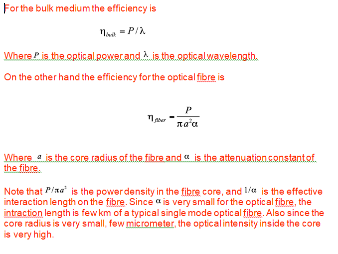
For the bulk medium the efficiency is
G656 – It is a single-mode optical fibre/fibre Optic which has the positive value of the chromatic dispersion coefficient greater than some non-zero value throughout wavelength band of anticipated use 1460-1625 nm.
It is similar as G655 optical fibre and considered as the wide-band Raman enabled fibre optic standard. It has minimum chromatic dispersion of 2 ps/nm-km at 1460nm, which enables good performance ( no non linearities ) for t signal channels, as well as Raman pumps at short wavelengths.
G657 – This optical fibre is low bending sensitive, it is capable of low values of macro bending losses at very low bend radii and is intended for use inside buildings or near buildings. It is compatible with ITU-T G652D fibres in access network.
Color code for fibre optic in optical fibre cable :- -Source Solinntech Shyampur Rishikesh
Position | Color |
1 | Blue |
2 | Orange |
3 | Green |
4 | Brown |
5 | Grey |
6 | White |
7 | Red |
8 | Black |
9 | Yellow |
10 | Violet |
11 | Rose |
12 | Aqua |
Difference between signal transmitting cables -:
Twisted/ parallel Pair Cable(JFC)/LAN | Co-axial Cable | Optical Fibre Cable |
Electrical signals travel through metallic conducting wire. | Electrical signals travel over inner metallic conducting wire. | Transmission in Optical form over glass wire. |
Made of metal conductor | Metal conductor | Glass or plastic |
Low data transmission | Low data transmission | High bandwidth and data transmission |
Installed by pulling or clipping | Pulling or clipping | Blowing and Pullling |
Electrical External Interference | Electrical External Interference | No External Interference |
Heavy and large diameter | Heavy and large diameter | Light and small diameter |
Small distance transmission | Small distance transmission | Long distance transmission |
High Attenuation | High Attenuation | Least attenuation |
: -Source Solinntech Shyampur Rishikesh
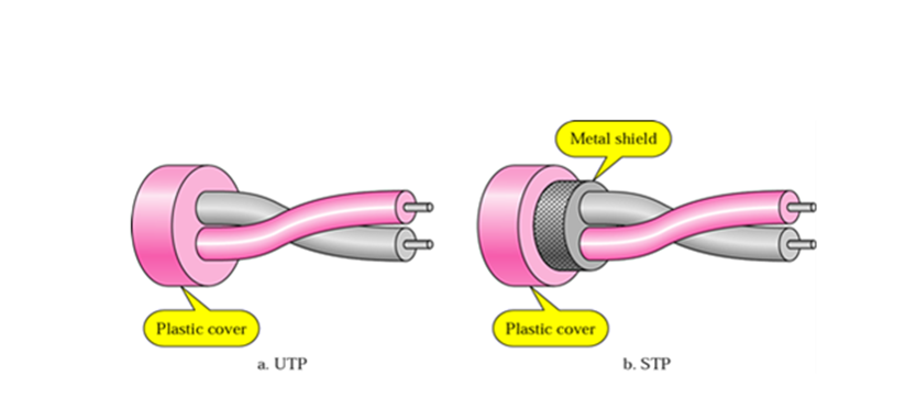
Twisted Pair Cable -:
In these cables, two conductors of one circuit are twisted together and considered one as forwarding circuit and another as return circuit. This design of twisting reduces noise from external sources, cross talks and sustains for longer time in telecommunication field.
It majorly has Shielded and Unshielded type of cable as shielded cable consists of foil jacket which helps to prevent crosstalk and noise from outside source. We generally use UTP for LAN connections in our Ethernet network.
Alexander Graham Bell patented twisted-pair wires in 1881.
How twist makes the difference??
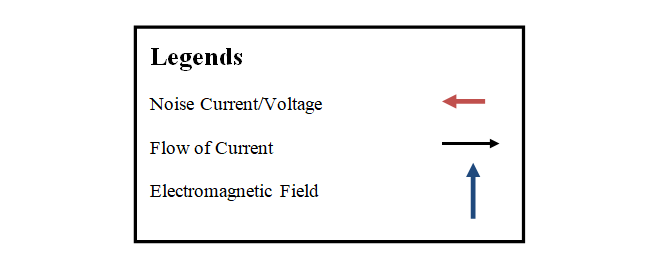
Concept to understand the flow of current and effect of EMF on parallel and twisted wire to understand the merits of twisted wires over parallel wires:-
The current flowing through wires in the closed circuit( from source to load ), induces the magnetic field perpendicular to the flow of current that result in induction of Electromagnetic force in the direction of flow of current and noises will be generated opposite to it.
: -Source Solinntech Shyampur Rishikesh
Considering the cases below:-
- Parallel Wires :-
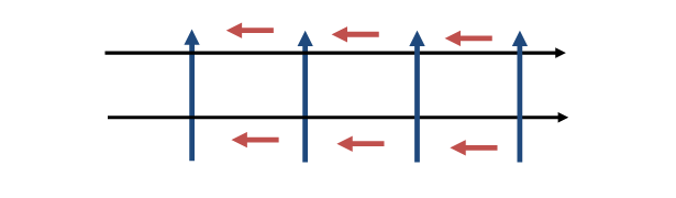
The induced noise current and voltage in one direction will be their in proportion to EMF.
- Twisted Wires :-
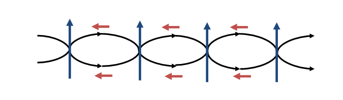
The change in the direction of wire, changes the EMF also and noise current and voltage also, both noise current and voltage of both the wires will cancel each other, hence least noise current and voltage will be remained.
Hence forth twisted pair of cable is better that parallel pair of cable.
: -Source Solinntech Shyampur Rishikesh
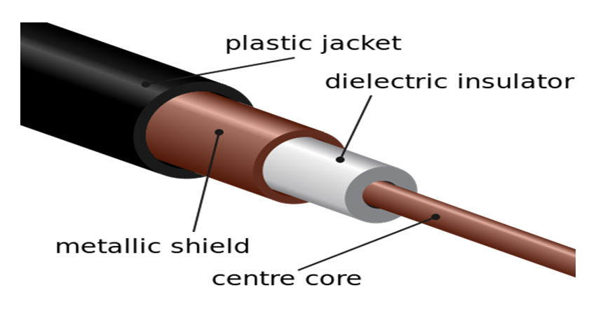
Co-axial cable:-
In these types of cable, there is the center conductor layer surrounded by dielectric insulator concentric with the center conducting wire. This di electric insulating layer is surrounded by conducting copper/ aluminum mesh that acts as ground for the assembly. This complete assembly is wrapped in insulating jacket that prevents electrical signals from external interference. These cables are used in CCTv, Telephones, Cables etc.
Optical Fibre Cables
For Overhead transmission line:-
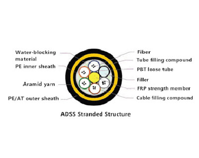
- ADSS Fibre Cable – All Di-electric Self Supporting optical fibre cables.These are self-supporting aerial optical fibre cables that requires no separate messenger wire between poles or towers to support the cables weight. These wires are alternative to Optical Power Ground Wires (OPGW) or Optical Attached Cable (OPAC) to reduce the installation cost. These cables are light in weight and small in diameter to reduce the load on the poles due to wind, cable weight.

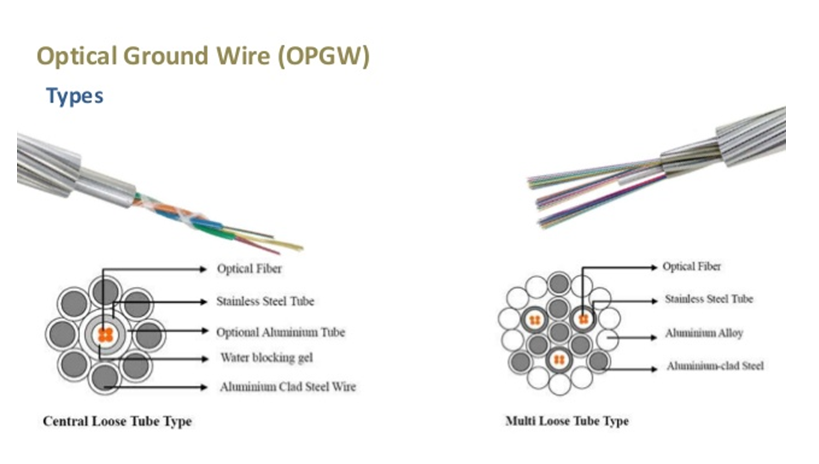
- OPGW – Optical Power Ground Wire. These type of cables serves two purposes communication and grounding. OPGW is laid in the top most position of the transmission line where it protects the circuit from lightning by providing a path to ground.
- These types of cable contains optical fibre cable surrounded by electrical conducting material, aluminium or steel wire that acts as ground wire during lightning and also support the weight of optical fibre cable for communication for longer distance between electricity pylons. OPGW is basically used between cities or states for the long distance transmission and are easy to install in place of optical ground wires as no digging is required.
Basic Telecommunication Network :-
- Backbone with Fibre network, Satellite and MW Radio Overlay
- GIS based ABD and network management
- Transport network – SDH/DWDM & POTS
- Router and Switches Backbone – Networking Layer
- Multimedia Communication System
- Multimedia Services – Telephones, phones, Internet
- Applications in all the systems : -Source Solinntech Shyampur Rishikesh
Steps:-
Route Survey
Trenching/OH
Duct Laying or OH accessories Installation
Blowing/Pulling
Splicing
Optical Testing
As Build Diagram
: -Source Solinntech Shyampur Rishikesh
Route Survey – Route survey is done before laying of the fibre optics, such that undulations can be prevented, sharp bending can be prevented, least splicing would be catered considering all the nodes or terminating point. To prevent any 90degree turn at sharp bend location, a chamber is installed and loop of fibre cable is left in the same.
Trenching/OH – Post route survey is finalized considering optimum number of chambers, shortest route of fibre optics, and feasibility of underground laying. The project is executed as for underground laying trenching is done and at no feasible location for underground laying, Poles are installed for Overhead fibre laying.
In UG laying, HDPE( High Density Poly Ethylene ) duct is laid and in OH poles are installed in specific distance and as per survey, Poles are installed with accessories to support, hold the weight of ADSS optical fibre cable and to prevent the bending of the fibre optic cable. Post all these installations below given points are executed and considered:-
UG laying – The underground fibre is blown through HDPE duct with help of jet machine that pushes the optical fibre cable(OFC) and compressor is also used such that fibre can be blown smoothly as it floats the Optical Fibre Cable inside the duct and make it easier to be pushed in the duct.
While using jet machine, the compression over fibre cable is considered such that Optical Fibre Cable may not get compressed with pressure of jet machine, nor bend loss be introduced in the fibre cable. In few locations where compressor is not feasible to be taken, Optical Fibre Cable is pulled in such locations with help of duct rodder that is connected with swivel connector, clevis ends etc.
OH Pulling – In this process, Optical Fibre Cable ADSS is pulled along the poles with help of manual pulling and attachment of Optical Fibre Cable with poles with help of OH accessories (Thimble eye nut, thimble bolt, turnbuckle, messenger strand, lashing wire, dead-end, support brackets, mid-span storage brackets etc.), these accessories prevent tension, suspension and maintains the bending radius in Optical Fibre Cable.
The wire rope messenger strand with small gauge of wire is used if the laid fibre in normal Optical Fibre Cable not ADSS. The strand is tensioned to satisfactorily withstand the weight of cable for the span length it is used and climatic loading like snow, wind, water etc. and in ADSS, the cable is self-supporting to withstand climatic loading and weight of cable.
Splicing of Optical Fibre Cable – Post the Optical Fibre Cable is laid, these different Optical Fibre cable drums are spliced together with splicing machine, for ribbon fibres we have ribbon connectors and for single core fibre we connects it with single core connectors.
Splicing is done very precisely and neatly to prevent from splicing optical losses like bubbling, splice with improper cleaving etc. Post the fibre fusion in the splicing machine, the joint is covered with sleeve and sleeve is further heated to protect any break in joint.
Splicing – It is the process of joining two fibre optic together. These are basically done by fusion splicing where both the fibres are welded with electronic arc inside the splicing machine. Splicing fusion process is given below:-
- First we do the physical preparation of fibre optic cable by removing all the protective layer of cable like cable jacket, strengthening fibre optic coating etc with help of tools like tubing cutter, Rotary cutter sitting and ringing tool, cable jacket stripper, paper cutter etc.
- The time fibre optic is exposed out of fibre optic cable we strips the buffer out of fibre optic with help of fibre optic stripper. Then with the help of Iso propyl and the tissue the fibre optic is cleaned properly to remove the remaining of the buffer such that fibre optic can settle down in the groove of splicing machine properly.
- Post proper stripping and cleaning of the fibre optic we need to cleave the fibre, mirror smooth and perpendicular to the fibre axis to obtain a proper splice with help of fiber optic cleaver. It has a rotatory blade that nicks the fibre perfectly perpendicular as possible.
- As proper stripping and cleaving is done, the fibre is now placed in the grove of the splicing machine splicing holder, depending on single fibre splice or ribbon fibre splice. That holder automatically aligns the fibre, only we need to put the fibre properly between and just behind the electrodes, it heats the fibre with help of electric arc generated between two electrodes and fibre gets fused together.
- Before the fibre is stripped as discussed in step first, we put in heat shrink sleeve to one side of the fibre. Post the fusion is over we bring the heat shrink sleeve over the fusion part and heat it in the heating chamber of splicing machine, to protect fibre from bending and tensile forces that will ensure the splice not to break during normal handling and from outside element and breakage.
- Now splice is over and to keep the splice secure we route it inside the tray of joint closure or fibre distribution management system.
: -Source Solinntech Shyampur Rishikesh
Optical testing:-
At the end of installation, the testing is done to check the proper installation of fibre optics and these testing finds out all the optical losses in the fibre optics cable such that those losses can be rectified.
Few of the testing are given below:-
- OTDR testing or splice loss/ bend loss testing
- Laser Source and Power meter testing to find the insertion loss
- Chromatic Dispersion test to detect the dispersion in fibre optic
- Polarized mode dispersion test to check the pole dispersion
- Attenuation Profile test to check the functioning through the bandwidth
Optical power loss at the splicing point is called as splice loss and optical power loss at the bending of the fibre is called as optical bending loss. The fibre optical power losses at the connectors end at transmission and receiving end is called as Optical insertion loss.
Splicing/ Bend loss – To detect the splice or bend loss, we uses a optical equipment called as Optical time domain reflectometer (OTDR). It gives us the distance of the loss from the testing location. We need to take the bidirectional traces from both the end points and to average both the losses to get the accurate loss reading. The broad and exclamatory OTDR traces are given below.
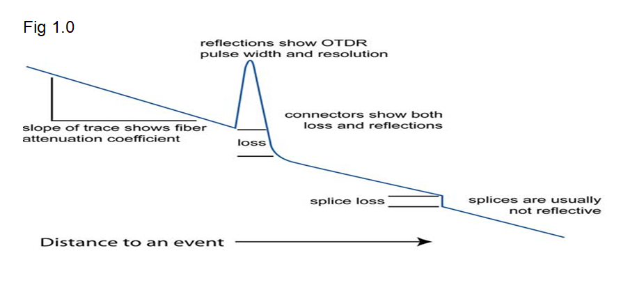
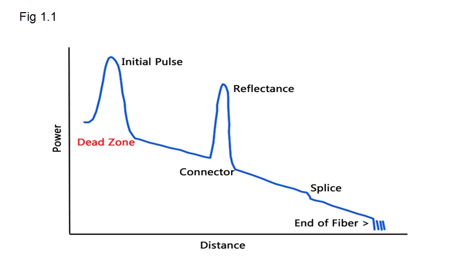
To be continued…………………….