Fibre Optics and its structure
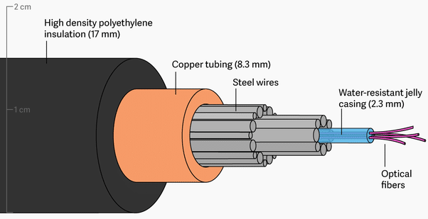
Fibre Optics is the medium for light to propagate. The Physical Structure of Fibre Optics is solid cylindrical rod that has 3 major components as given below -:
Note* considering fibre is made of Silica Germanium
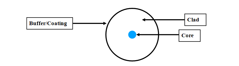
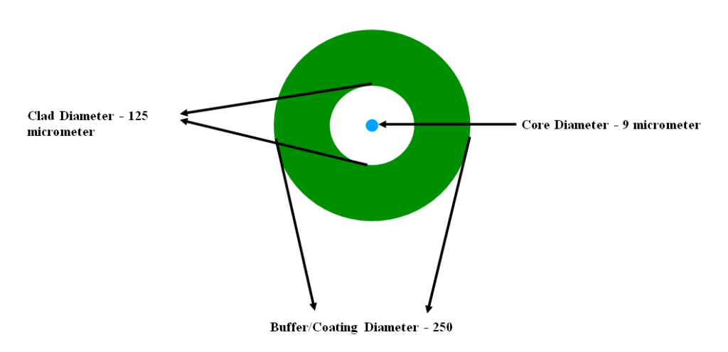
Core – The inner most part of the fibre optics is core, through which light travels and it is made of silica.
Clad – It is over the core, that guides the light to travel within core. It is kind of waveguide in fibre optics that allows light to propagate in particular pattern and direction.
Buffer/Coating – Fibre optics consist of core and clad, where light propogates, as these both components are very delicate to handle and cannot bear shocks and vibrations. Hence these are protected with a protection layer called as Buffer/Coating that protects fibre optics from shocks, moisture, scratches, cracks etc. It is made of Acrylate or carbon or polyimide, depending upon the condition where fibre optics is to be laid.
Medium – Anything or substance through which things are conveyed or in reference to fibre optics, it is the substance through which light is travelling.
Composition of Fibre Optics – It can be either made of plastic, Plastic clad silica(PCS), Silica and silica germanium etc, composition is the major factor that defines the quality of output signals with respect to input signals, weather the signals will be distorted or in same phase difference or their is some time delay. Fibre Optics construction defines the strength and quality of signals at output.
How fibre works and Reasons for attenuation -
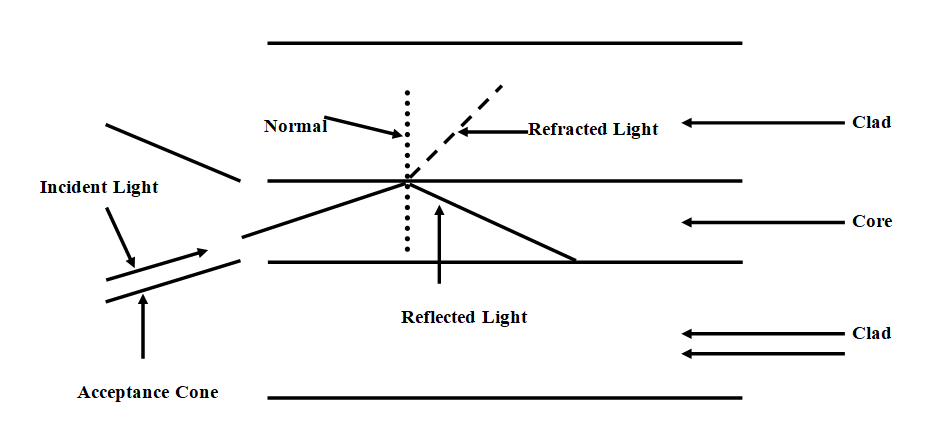
Light is sent from source through the acceptance cone to the fibre such that light may propagate with the maximum intensity and retain in core. Traveling of light depends on the refractive index of medium, so the refractive index of the core is always higher than the refractive index of clad such that clad could reflect most of the light and let it to travel within core.
As whenever light travels from high denser medium to low denser medium, light travels away from normal and after critical angle, light starts reflecting other than refraction and this is the way light propagates in fibre optics.
Modes of Fibre Optics :-
Propagation Mode -:
- Single Mode Fibre Optics
- Multi Mode Fibre Optics
Both the above modes provides different performance with respect to attenuation and time dispersion.
Single Mode fibre optic provides better performance than multimode fibre optic and at higher cost. Mode of fibre optics depends upon dimension of fibre optics and variation of indices of refraction of both core and cladding across cross section.
Index of refraction = 1 / Velocity of light in medium / Velocity of light in vacuum.
Single Mode of Fibre – It is the type of fibre that is designed for the transmission of the single ray or the mode of light through it. Dispersion in single mode fibre is next to zero in comparison with multimode fibre with respect to distance. It is used for long distance signal transmission.
Single mode fibre optics has two primary sources of specifications of single mode optical fibre.
1st – ITU-T defines as G65 * x series
2nd – IEC 60793-2-50
There are nineteen different single mode optical fibre specifications defined by International Telecommunication Union – Telecommunication Section (ITU-T).
Name | Type |
ITU-T G652 | G652A,G652B………..C,D |
ITU-T G653 | G653A, G653B |
ITU-T G654 | G654 A ……..B,C |
ITU-T G655 | G655A, G655B……….G655E |
ITU-T G656 | G656 |
ITU-T G657 | G657A………B, C, D |
Characteristics as per ITU-T :-
Fibre Type | Characteristics |
G.651 | Characteristics of a multi-mode Optical fibre cable |
G.652 | Characteristics of a single-mode optical fibre and cable |
G.653 | Characteristics of a dispersion-shifted, single-mode optical fibre and cable |
G.654 | Characteristics of a cut-off shifted, single-mode optical fibre and cable |
G.655 | Characteristics of a non-zero dispersion-shifted single-mode optical fibre and cable |
G.656 | Characteristics of a fibre and cable with non-zero dispersion for wideband optical transport |
G.657 | Characteristics of a bending-loss insensitive single-mode optical fibre and cable for the access network |
G651 – The ITU-T G.651 is an MMF with a 50 micro meter nominal core diameter and a 125 micro meter nominal cladding diameter with a graded refractive index. The attenuation parameter for G.651 fibre is typically .8 db/km at 1310 nm. The main application for ITU-T G651 fibre is for short-reach optical transmission systems. The fibre is optimized for use in the 1300-nm band. It can also operate in the 85-nm band.
G652 – Recommendation ITU-T G.652 describes the geometrical, mechanical and transmission attribute of single mode optical fibre and cable which has zero dispersion wavelength around 1310 nm. The ITU-T G.652 fibre was originally optimized for use in 1310 nm wavelength region but can also be used in the 1550nm region ( where this fibre is not optimized ). Both analogue and digital transmission can be used with this fibre.
G652A and B – These two type of fibres from G652 family have a zero dispersion wavelength point at 1310 nm, which allows them for operation in the 1310 nm band. But if we consider them for WDM technology, they are not suitable for the spectrum due to water peak.
What is water peak ?
Water Peak is defined as the peak in attenuation in optical fibres due to contamination from hydroxyl (OH) ions that are residuals of the manufacturing process. It causes high attenuation and pulse dispersion.
G652C and D – These two type of fibre from G652 family are more advanced and refined as these fibres are optimised with elimination of water peak for spectrum operation like in WDM technology. This optimisation makes them effective at wavelength between 1310 to 1550 nm to support WDM.
G652D single mode fibre has superior Polarized Mode Dispersion parameters in comparison with G652C fibre, hence known as Standard single mode fibre (SSMF) and can easily supports 10 GbE and 40GbE systems.
G653 – It is also called as Dispersion shifted fibre (DSF).This type of optical fibre is made to optimise both low dispersion and low attenuation in optical fibre. In this optical fibre, core and clad index profile is tailored to shift the zero dispersion wavelength from 1310 nm in G652 family to the minimum-loss window at 1550 nm.
In fibre optics both material dispersion and waveguide dispersion affects the propagation of light. So in this fibre, waveguide dispersion is made for negative by changing the index profile and thus be used to offset the fixed material dispersion, shifting the overall dispersion.
This optical fibre allows communication system to posses both low dispersion and low attenuation but when used in WDM technology, dispersion-shifted fibres suffer four wave mixing effect which causes inter-modulation of the independent signals sent from transceiver end. Hence G652 single mode fibre is often used by all the operators all across the globe.
Four-Wave Mixing – In WDM system with multiple channels, one important nonlinear effect is four wave mixing. Four-wave mixing is an inter-modulation phenomenon, whereby interactions between 3 wavelengths produce a 4th wavelength.
In a WDM system using the angular frequencies ω1,….ωn, the intensity dependence of the refractive index not only induces phase shifts within a channel but also gives rise to signals at new frequencies such as 2ωi-ωj and ωi + ωj – ωk. This phenomenon is called four-wave mixing.
The four-wave mixing effect is independent of the bit rate but is critically dependent on the channel spacing and fibre chromatic dispersion. Decreasing the channel spacing increases the four-wave mixing effect, and so does decreasing the chromatic dispersion. Thus the effects of Four-Wave Mixing must be considered even for moderate-bit-rate systems when the channels are closely spaces and/or dispersion-shifted fibres are used.
G654 – It is also called as cut-off shifted single-mode optical fibre and cable.
This fibre is best choice for long (300-400 Km) un amplified span and is optimised for coherent transmission systems. The combination of ultra-low loss and increased nonlinear power limit lowers system costs and simplifies the upgrade path to 400G and 1T in the C and L band. Its core is made of pure silica dioxide. It provides lower system cost for greater than 10G enabled by avoiding or reducing signal regeneration, longer spans between amplifiers.
This single-mode optical fibre has the zero dispersion wavelength around 1300nm, which is loss-minimised and cut-off shifted at a wavelength around 1550 nm and which is optimised for use in the 1530-1625 nm region. It can be used for long-distance digital transmission applications, such as long-haul terrestrial line systems and submarine cable systems using optical amplifiers.
Cut-off wavelength – The wavelength greater than which a particular waveguide mode ceases to the waveguide mode.
Optical Wavelength Bands:-
In optical fibre communication system, transmission bands have been defined and standardised.
- O-band : 1260-1360nm ( Original Band ).
- E-band : 1360-1460nm (Water peak band ).
- S-band : 1460-1530nm.
- C-band : 1530-1565nm ( Bands used by the higher performance systems ).
- L- band : 1565 – 1625nm ( Bands used by the higher performance systems ).
- U/XL-band : 1625-1675nm ( Not used )
G655 – It is also called as Non Zero Dispersion Shifted Fibre (NZDSF). It is because the dispersion at the wavelength of 1550nm is close to zero but not zero. It has a small, controlled amount of chromatic dispersion in the C-band (1530-1560 nm), where amplifiers work best and also has higher core area. It is positive dispersion and negative dispersion NZDSF, positive dispersion can suppress four-wave mixing and other non linear effect. Negative and positive dispersion is defined as negative and positive slope versus wavelength.
Non Linear Fibre Optics – When Optical power intensity inside an optical fibre increases, the refractive index of the fibre gets modified. The wave propagation characteristic becomes a function of optical power. Unlike linear fibre optic as, where the propagation constant is a function of fibre and the wavelength only, the propagation constant becomes a function of optical power in addition to the other parameters. Inside a single mode optical fibre, an optical power of few tens of mW may drive the medium into non-linearity.
When non optical fibre becomes non-linear the pulse propagation gets significantly modified. Also new frequencies get generated inside the optical fibre. The spectrum of the output signal is not same as that of the input signal.
Although to observe the non-linearity in the bulk medium generally a large optical power is required. Whereas, optical non-linearity can be easily observed inside an optical fibre with very low optical power of few tens of mW. This can be explained as follows.
The efficiency of non-linear process is proportional to the optical intensity (optical power per unit area) ant he interaction length.
For the bulk medium the efficiency is
Find it in our next blog Fibre Optics 2 – Optical Fibre Cable…………to be continued……………..